Posts on Social Networks
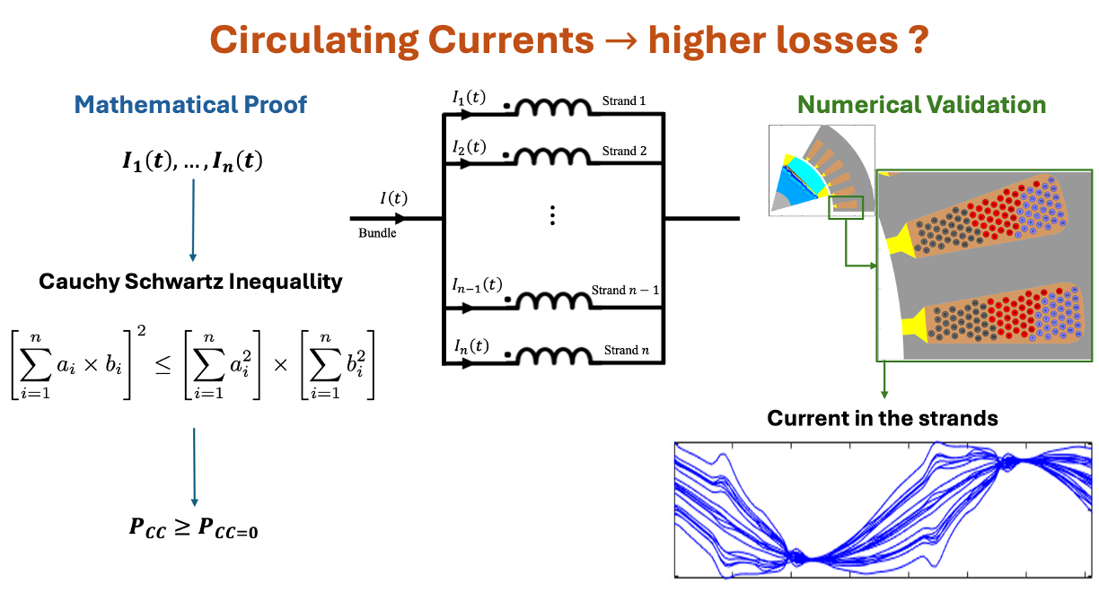
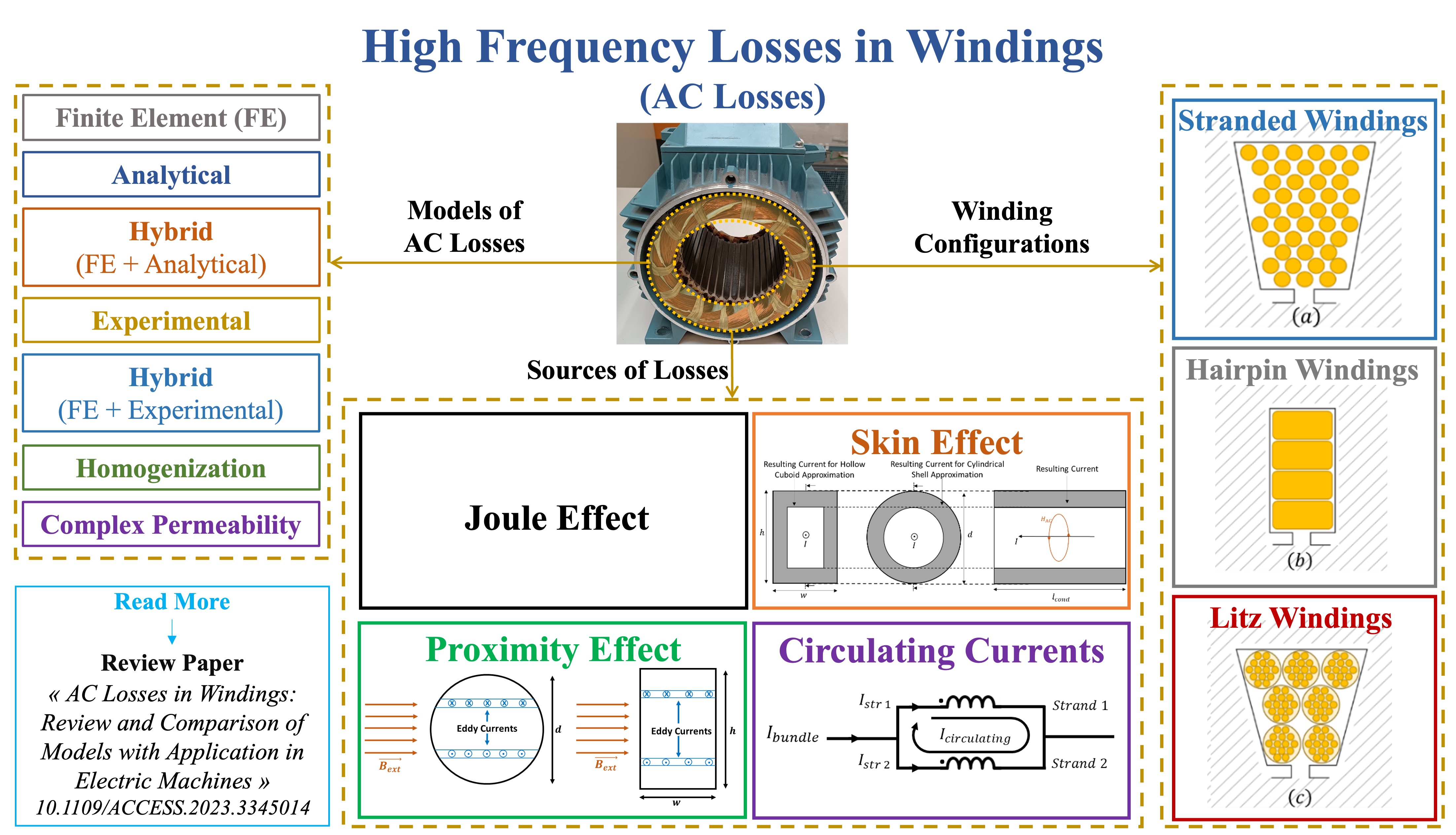
◽ Definition: Circulating currents are unwanted currents that flow between the parallel-connected conductors of a winding even at no-load.
◽ Causes: Circulating currents occur between parallel-connected conductors of an electric machine’s winding due to asymmetries and the different placements of the parallel strands inside the slot.
▪️ Property: It is intuitive to claim that this effect will lead to higher losses compared to the DC case, which is also predicted by the numerical calculations and the experimental results.
▪️ Mathematical Proof: Theoretically, this fundamental property of circulating currents is demonstrated mathematically in the general case using Cauchy Schwartz Inequality. The property and the proof were initially stated and presented in this article, but are presented in a mathematical framework and context in this article.
👉 Read More:
📜 Mathematical Proof of the Property
📜 Review Article on AC Losses
📝 LinkedIn post
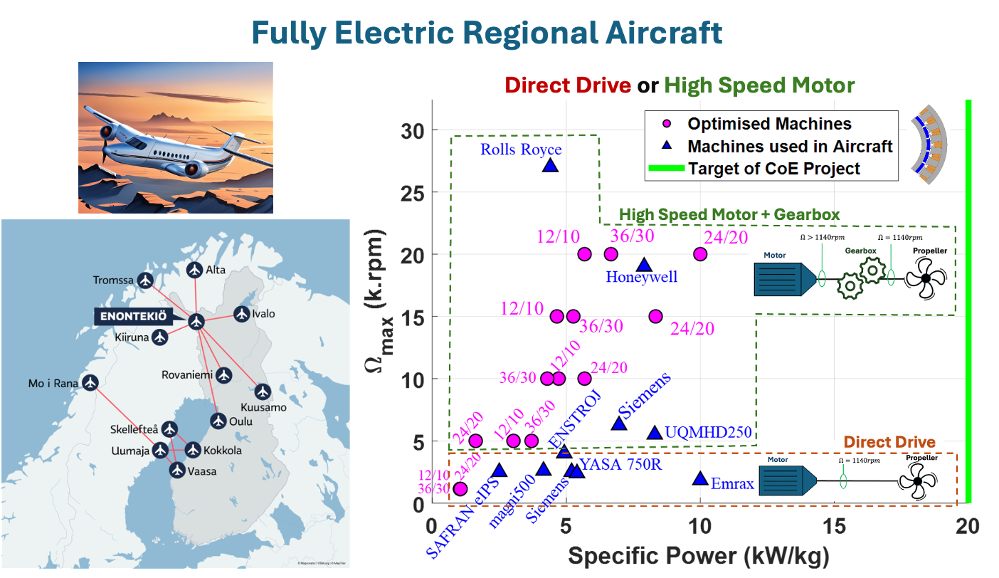
Regional electric aircraft 🛩️ offer the potential to connect remote and hard-to-reach areas, as seen in Finland’s project to link cities in challenging Nordic regions. A critical focus in electric aircraft propulsion is increasing specific power, with a target of 20 kW/kg, as defined by the HiECSs Centre of Excellence project. To achieve this, two primary options are being explored:
🟧 Direct Drive: The motor is directly connected to the propeller, operating at the same speed (around 1,140 rpm).
🟩 High-Speed Motors: Operating at higher speeds requires a gearbox to match the propeller’s speed.
📈 We optimized these two options for regional fully electric aircraft specifications and compared the total weight, considering the gearbox. Results revealed that the total weight (motor + gearbox) reaches a plateau between 10,000 rpm and 15,000 rpm, offering no further improvement in specific power beyond this range. Therefore, increasing the motor’s speed is beneficial only up to 10,000–15,000 rpm.
👉 Read More:
📜 Research Article
📝 LinkedIn post
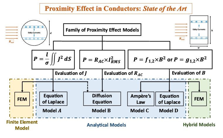
Proximity effect in conductors are due to an external magnetic field that induces eddy currents. These eddy currents generate losses named ‘Proximity Effect Losses’ or ‘Strand-Level Proximity-Effect Losses’, which can be evaluated using various models. The family tree of the main models in the literature is represented in the figure below. This article reviews and classifies the main models in the literature allowing for the evaluation of proximity effect losses in conductors for both circular and rectangular shapes. Amongst these models, you can choose the suitable one based on your application.
👉 Read More:
📜 Review Article
📝 LinkedIn post
For high frequency each effect, prior comparisons reveal the optimal model offering a good trade-off between computation time and accuracy:
🔹 Skin Effect: Analytical Models are fast and provide accurate results.
🔹 Proximity Effect: Analytical Models can be used when considering Armature Reaction only. For On Load condition, Hybrid Models are indispensable to account for various sources of magnetic field in cases of random geometry and frequency.
🔹 Circulating Currents: Finite Element coupled with a Circuit Model is unavoidable in cases of random geometry and frequency.
👉 Read More:
📜 Review Article
📝 LinkedIn post
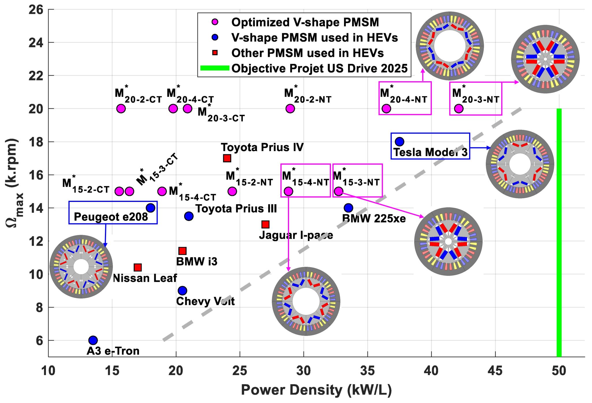
📊 The use of new technologies (high fill factor, high current density, and thin laminations) with speed lower than $20,000 rpm$ is a better alternative for high power density regarding the traditional automotive bearing limitations. Research work need to be focused on cooling techniques to evacuate high losses due to increased current density and fill factor.
👉 Read More:
📜 Research Article
📝 LinkedIn post
